Planetary stratigraphy
English
Henrik I. Hargitai: Planetary stratigraphy - an introduction. Teacher’s handbook.
Download original PDF · All handouts (PDF)
Handbook text and figures
PLANETARY STRATIGRAPHY
– AN INTRODUCTION
TEACHER’S HANDBOOK
Henrik I. Hargitai ELTE University, Budapest, Hungary
Goal: Identify the elements of the planetary surface using spacecraft images and infer surface evolution from systematic morphologic and stratigraphic analysis of structural landforms, geologic units and albedo features. Method: We show images (image mosaics) that are analyzed by making a geologic sketch map. Without direct information on the material of surface rocks and historic data on surface events, we reconstruct surface geology from morphology, the shapes (relief) and patterns of the terrain. We distinguish between observations and interpretations. For observations, we use a descriptive vocabulary, and for interpretations we assign geologic processes to the identified units. Finally, we reconstruct surface evolution using the principles of stratigraphy and morphologic differences.
1 Preparation 1.1. - Distinguish negative from positive relief. (You may skip this part) 1.2. Distinguish old from new surface 2 TESTING SKILLS ON FAMILIAR OBJECTS (you may skip this part) 3. BEGINNER LEVEL PHOTOINTERPRETATION 1 PREPARATION 1.1 (You may skip this part) Distinguish negative from positive relief. This is a basic requirement for correct geologic interpretation. The relief can be determined from shadows and shading or a DTM (Digital Terrain Model) of the region corresponding to the image. To be able to answer question 1), you need to determine the direction of the source of illumination. In other words, for optical images: Where does the Sun shine from? (For radar images: Where the scene is illuminated from by the active radar instrument?) 1.1.1. SEEING RELIEF CORRECTLY
Problem: You need to identify shadows (dark areas) and shading (grey areas in half-shadow). Dark shadows and shading is different from dark albedo surfaces where the color of the surface is dark. The illumination comes from the direction opposite to where the shadows are cast to. Teacher narrative: We will use shadows to determine the relief on the scene. THE PROBLEM OF OPTICAL ILLUSION: In spacecraft images it is difficult to distinguish high standing circular mounds/cones from circular depressions because there are no familiar landmarks in the scene. In these images the relief is often inverted when we turn the image upside down. It is, therefore, essential to find a familiar landform that can be used for determining the relief correctly. Student instruction: Look at the two figures on handout 1_1. Are linear features deep cracks or high ridges? Are circular features depressions/craters or mounds?
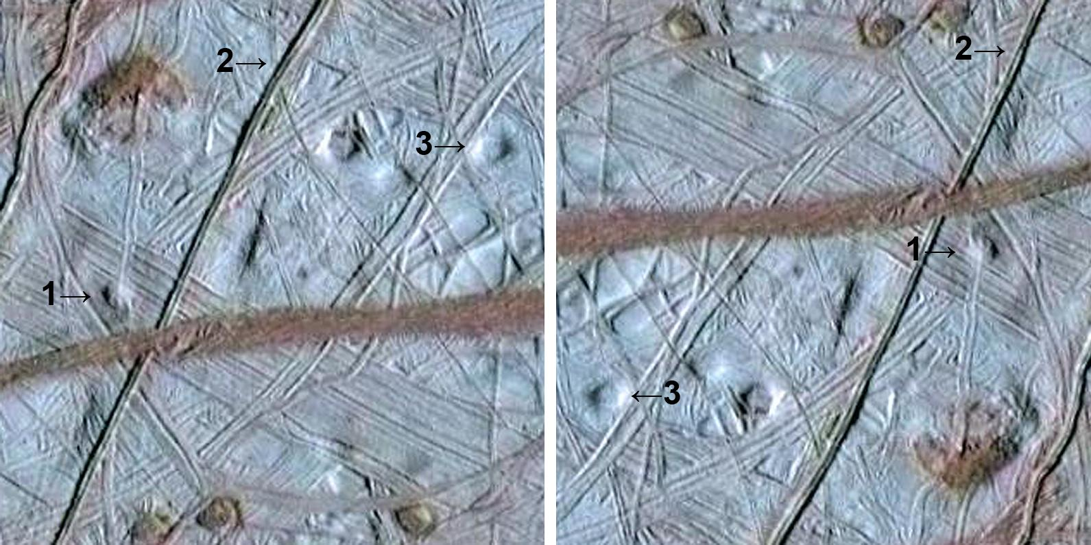
Handout_1_1 The two images (of the icy moon Europa) show the same scene but upside- down. Is the relief inverted? Which one might be the real relief? ANSWER: You may only be able to answer this if you know the direction of illumination because there are no familiar objects on the image. The correct answer is: 1 is a dome, 2 is a ridge, 3 is a depression. The direction of the illumination can be read from the spacecraft image data label, or have prior geologic knowledge of the geology of Europa where most linear features are ice ridges built by water pressed out of cracks from the subsurface ocean and frozen on the surface. In most cases, however, circular forms are almost all craters.
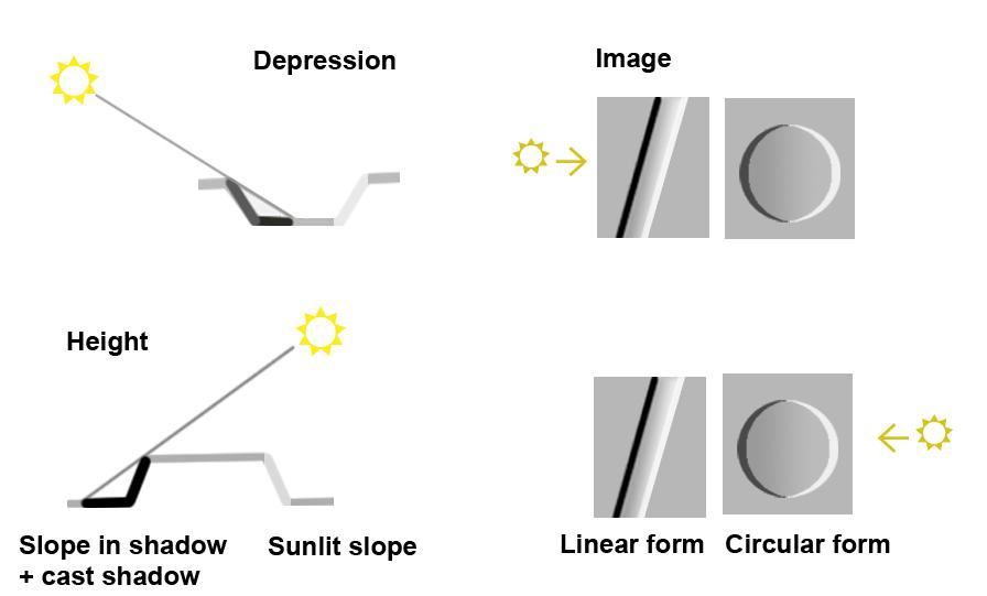
Handout_1_2 TEACHER NARRATION OF THE FIGURE. This figure explains the relationship between the direction of illumination, shadows /shading and relief. The same image can result from two different relief situation depending on where the illumination comes from. Without familiar objects, or knowing the direction of the Sun, we are unable to determine the correct relief. The left hand part of the figure shows relief from the ground as a cross section while the right hand side shows the same objects from above as seen on a spacecraft image. The upper part shows how depressions would look like, and the lower part shows elevations. 1.2. Distinguish old from new surface You will have four tools to determine which unit is older. Results from the four tools should be consistent with each other. 2.1. Stratigraphy, the law of superposition states that the unit that covers (overlies) another one is the younger of the two. 2.2. Stratigraphy, The principle of cross-cutting relationships. The feature that cuts through/into another one is the younger of the two. 2.3. Crater density. A unit with denser impact cratering is older than one with less craters per unit size, because it was exposed to impact cratering for longer times.
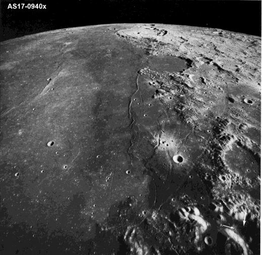
Handout_1_4 QUESTION: Which is older, the right or he left hand side of this image (of the Moon)? ANSWER: The smooth, dark mare (lava plain) is younger (left side – it has only few, small craters). The rough, densely cratered highland terrains are older (right side). The rough surface is the result of crater depressions and crater ejecta on the top of each other. 2.4. Morphology (degradation): a feature with subdued topography is usually older than a feature with sharp outlines.
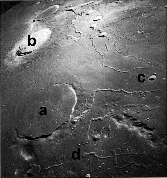
Practice on Handout_1_5 : put the craters a–d into chronological order (Rimae Prinz region, Moon). Solution: from oldest to youngest: a, b, c; while d is not a crater, it is a collapse source pit of a lava flow.
2 TESTING SKILLS ON FAMILIAR OBJECTS (you may skip this part) Practice with this figure.
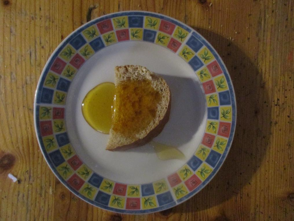
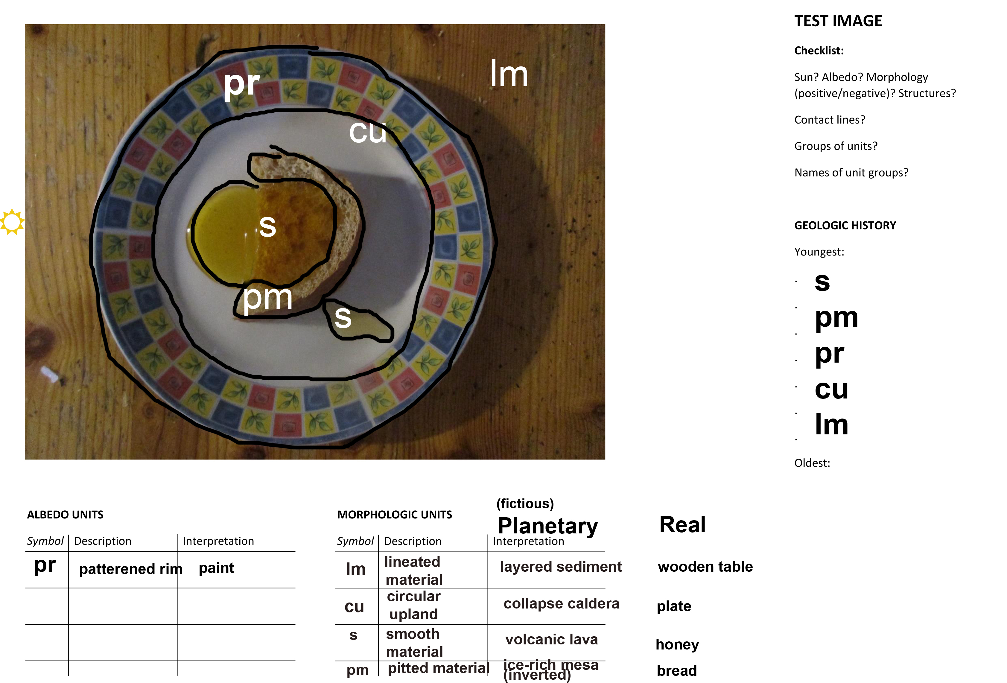
Handout_2 TEST FIGURE FOR GEOLOGIC MAPPING 2.1. LEARN HOW TO DETERMINE THE DIRECTION OF THE SUN Student instruction. 1. Determine the direction of the source of illumination using shadows. Draw a “sun” figure / Show where the illumination comes from. 2.2 IDENTIFY GEOLOGIC UNITS (PHOTOINTERPRETATION) Handout_2.pdf DISCUSSION In this task, discuss the following topics: 1. Ask: What types of features (“landforms”, regions, linear and point features) can be distinguished by appearance. Units or landforms may be different in albedo (brightness), color, shape (relief) or pattern. Note that you can distinguish “shadow and shading” color units but they do not correspond to any material units. 2. Ask: how these units may have formed (formative process – how they were emplaced in the present location) (“intuitively”, not knowing which is which). 3. Ask: Which of these features are the youngest and oldest. Put them into chronological order based on when they were “emplaced”, or placed in the scene. This is called the law of superposition: layers at higher positions are younger than layers at the bottom. NB: the original material age of the objects in this test scene are different from “emplacement” age. We only discuss emplacement age, not material age here. In nature, emplacement age is typically the same as the material age.
3. BEGINNER LEVEL PHOTOINTERPRETATION Identify the different units (by appearance), mark them (with outlines or color) and put them into chronological order (a= youngest, b= older etc.) (see 1.2 for more information) and try to make a narrative (story of surface evolution). 3.1 BEGINNER IMAGE 1
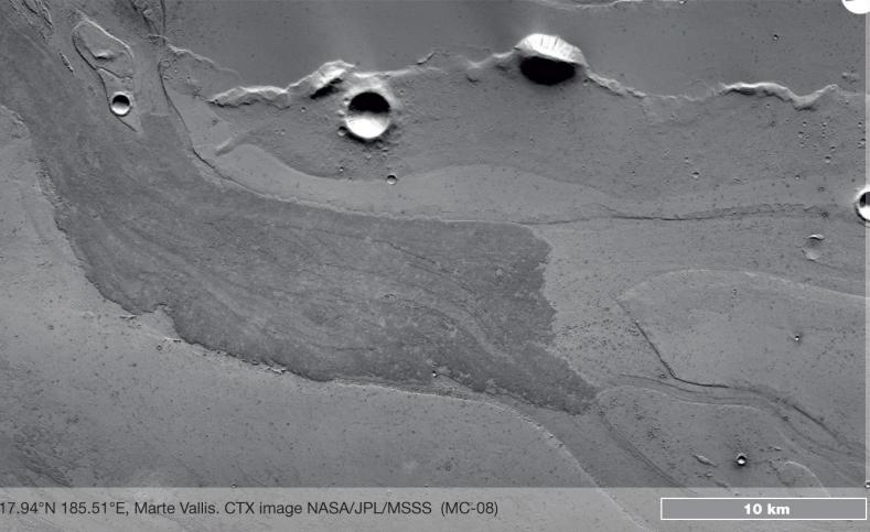
SOLUTION
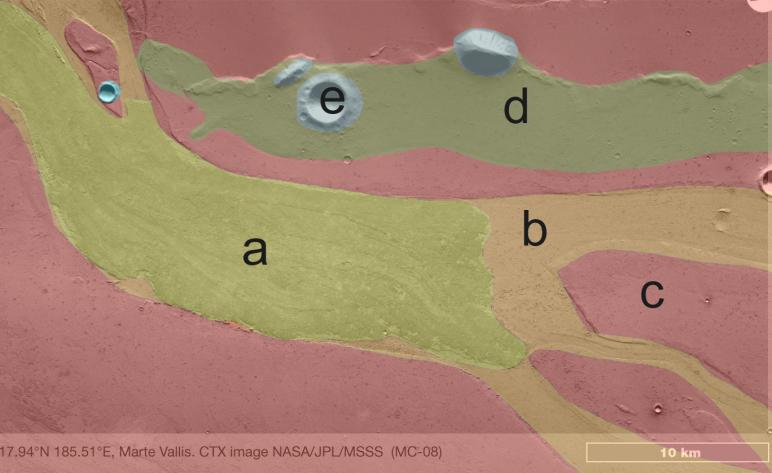
Marte Vallis. On this image lava flows into an outflow channel. In the lava flow there are only

very few craters. It suggest
s
that the flow is very young. The lava (a) flows onto the channel bed


(b): the channel is older. The channel cut into a plain, whose material was preserved in

streamlined islands (c) and the overbank region (c). A large crater (e) and a hill stands on a

higher level, which is probably older than the surrounding materials (it has more craters
). The


hill and the large craters are the oldest features in this image. If you observe closely (at the lava

flow margins), you can see that the dark tone of the lava flow is just a surface deposit: the lava is

not dark. Age of lava flow: 20 million years.

3.2 BEGINNER IMAGE 2
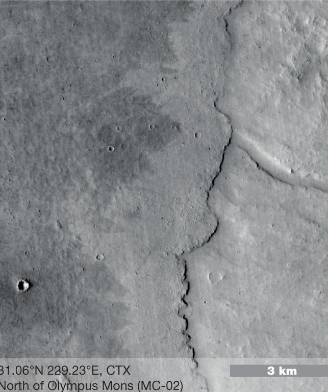
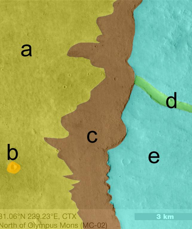
North of Olympus Mons. There are three levels on this scene
→
. The lowest one is the channel


floor (d), the middle one is the channel’
s overbank (e), and the highest one is the material on the


left side (c). The channel (d) cut into (e) so the channel is younger than (e). Deposit (e) was

flooded from the left side by a thick layer of new material. Its lobate margin is typical of lava

flows. The channel (d) is cut into a previous lava flow: probably it is a lava channel. It continues

now under the new lava flow. A small, 300 m di
ameter impact crater (b) in this new lava flow


likely impacted into the young lava flow. The youngest feature is the dark marking (a) on the top

of the lava flow. This dark layer is the result of recent winds that cleared dust from that area. Age

of lava flooding: 100 million years.

3.3 BEGINNER IMAGE 3
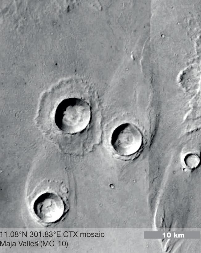
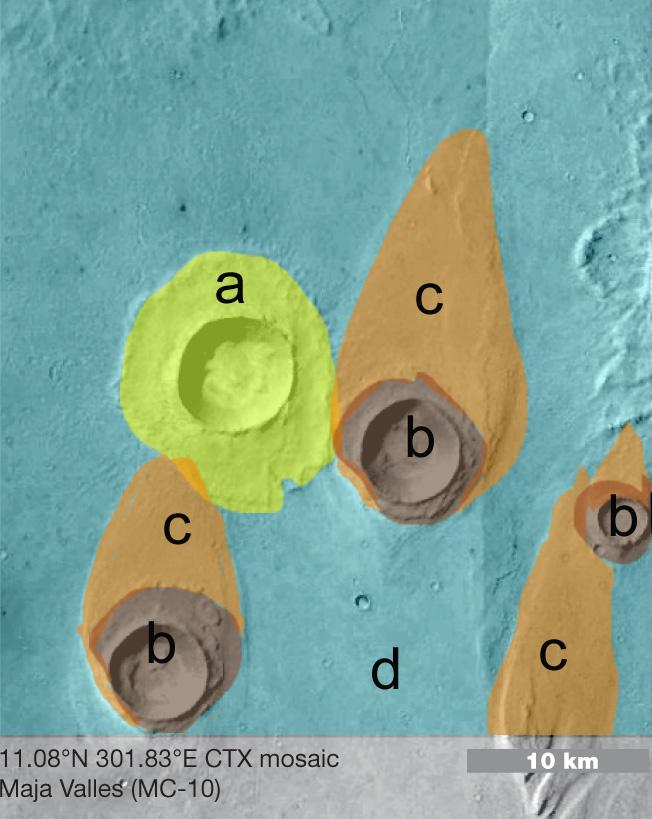
Maja Valles.
This scene is in the middle of a large outflow channel. The image shows three large


craters and deposits around them. One has an almost circular deposit (a), the others’ are

streamlined but a small circular deposit is also visible. The streamlined deposits are covered by

the circular one (b), so the lower, streamlined
is older (c)
–
but the streamlined
is
material
form


younger! After the older craters formed, on t
he top of a layered material, the region was flooded


by fast
-
flowing water that eroded away most of their ejecta, and also a thick layer of the


underlying surface (c) into which the craters impacted. Some of this surface was preserved in the

“shadow” of the water current (behind the craters), and was cut into a streamlined shape by the

flood (c). In other parts, the flood eroded away this layer (d). The youngest crater (a) was not

exposed to the flood, it formed afterwards. Age: 2
–
3.5 billon years.


3.4
BEGIINNER IMAGE 4


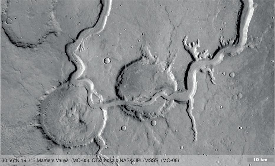
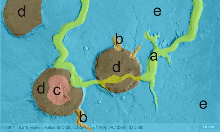
Mamers Valles. One long and deep channel (a) is making its way through older, eroded craters

(d). The channels have short branches and amphitheatre
-
like heads that may form by seepage.


The old craters are filled with some deposit (d, e). The left side crater has
hills (c) in it, suggesting


that some deposit may have filled it in the past. The channels in this region are called fretted

channels. They were formed by water floods. Later they were filled with ice, which may still be

there. There are two sets of channels: one ends at the bottom level of the craters (b). This sugges

that they carried water or ice and sediments into the craters. The other (a) is eroded deeply into

the craters: this channel form and the deposit within the channel are the youngest featur
es. How


could this channel cut through the high crater walls? Probably by incision, cutting itself deep into

a now
-
eroded surface. Age of channel: 3.6 billion years.


4 ADVANCED LEVEL TEST IMAGE – DRAWING
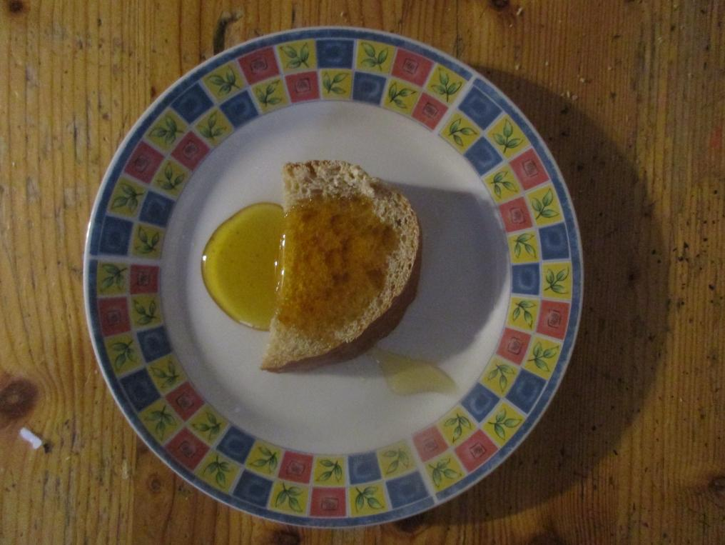
Now let students “Map” the Test image using Handout_2.pdf copies, and/or on the whiteboard where the image is projected or drawing a sketch map on a blackboard. 5. Ask: Now draw “contact lines” between the units: trace the outlines of the features. 6. Aks: Now label the units (features) enclosed by the lines. Use abbreviations of the unit names, for example “cf” for “circular feature”. Use descriptive words that describe the appearance (e.g., pitted object”), and not interpretive words (e.g., “bread”). Pretend that you don’t know what is on the image. 7. Ask: Now put the units in chronological order. 8. Check the sample solution by displaying Handout_2_key.jpgfile with a projector. Now repeat this task using a real image, TEST PLANETARY IMAGE - Handout_3.pdf.
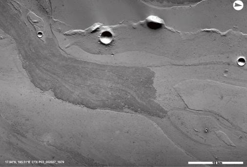
9. Ask: what types of features and units (landforms, regions, linear and point features) can be distinguished by appearance? Units or landforms may be different in albedo (brightness), shape, relief or pattern. (discuss) 10. Ask: how these units may have formed (formative process)? (discuss) 11. Ask: which of these features are the youngest and oldest? (discuss)
DRAWING You may again use whiteboard / blackboard with one student, or handout photocopies for each students.
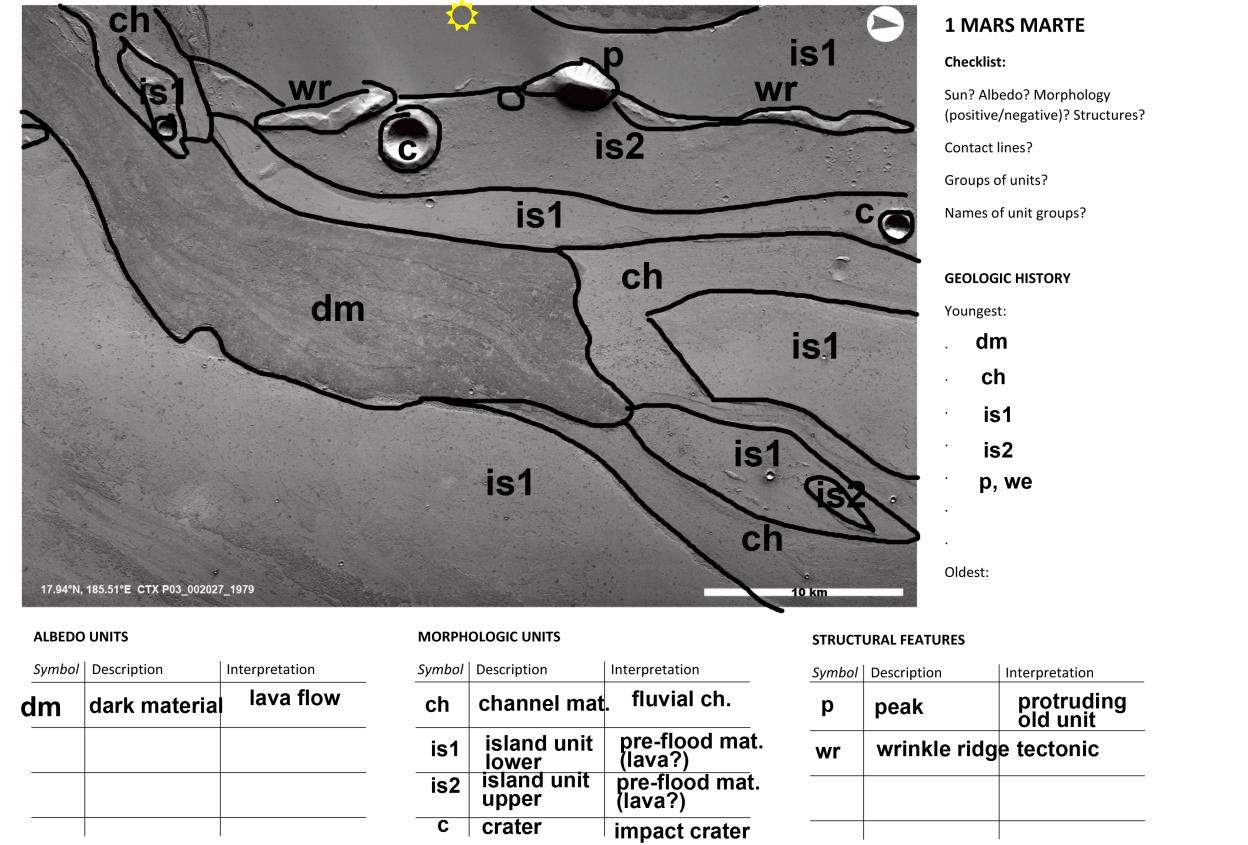
12. Classify surface geology. 12.1 Contacts. Draw contact lines: Trace the boundaries between different terrain using lines of one color. Geologic units enclosed within contact lines comprise of 3D bodies of a particular material that was emplaced in one geologic event and have uniform modification history. Some units can be identified from its albedo, others from their shape or relief. Do not take into account very small sized units, trace only the major, most prominent units. You may color each unit types with different color fills. 12.2 Structures. Draw the center lines of the most prominent structures with a different color. Structural features have no material unit because they were formed by distorting or removing existing materials. Structural features include cracks, channels or ridges. Albedo and morphologic units occupy a given area whereas structural features are typically line features. Trace the middle line of structural units. Structural units may be depressions or ridges, interpreted as channel, valley, tectonic trough, compressional ridge etc. 12.3 Fill in the tables: Description and interpretation. Determine the most likely formative process of each unit and structure type. Similar looking units should be grouped into the same unit (if they are at similar stratigraphic position) - they likely formed at once. 12.3.1 Separate your units into albedo (reflectance/spectral) units and morphologic units. 12.3.1 What goes to “albedo units”? Material units that are distinguished predominantly by its inherent reflectance (color, brightness or color pattern) from the adjacent units. Do not take into account brightness differences caused by different illumination (or shading). Albedo difference suggest different materials or grain size (for radar images, brightness differences are caused by different particle size - dark are smooth, bright are rough, rocky terrain).
12.3.2 What goes to “morphologic units”? Material units that are distinguished predominantly by its shape or topographic pattern. Example: smooth, rough, peak, rippled, cratered, etc. Morphology is revealed from shadows and shading. 12.3.2 What goes to “structural features”? Features that has no specific material associated with, but that has a prominent shape, or relief (see 12.2). 12.3.3. What goes to “description”? Describe the above units with descriptive words. These need only a vocabulary but no geologic knowledge. Description terms may include roughness (smooth, rough), reflectance (bright, dark), relief (depression, height), shape (straight, sinuous, circular, lobate, polygonal, zigzag) etc. Do not include words that suggest a specific origin. 12.3.4 . What goes to “interpretation”? Provide an interpretation of the units’ origin or formative process (“speculate”) based on terrestrial analogs and geologic context. This task requires prior geologic knowledge. Interpretation terms may include the name of material (e.g., lava, sand, dust, ice etc.), and formative process (aeolian [by wind], fluvial, lacustrine/marine, impact, tectonic, volcanic, airfall, etc. Here is a table of hints to origin
Shape, pattern Typically formed by ... (Process) Typically is made of (material)
tectonics (graben, fault) ---
Straight or curved line (crack, trough)
Sinuous line (valley, channel) fluvial / volcanic ---- / lava
Lobate “petal” like unit impact fluidized ejecta (breccia)
impact crater rays
Ray like spikes radiating from a circular depression
Repeated ripples, wave like pattern aeolian (wind-formed) dunes sand
Polygonal pattern permafrost (ice) ice rich subsurface regolith
Lobate pattern flow of viscous material glacier (ice) or landslide (debris) or lava flow (lava) Circular depression Impact, collapse, sublimation ---
subdued - rolling morphology blanket from airfall ash, dust
fan shaped deposition fluvial delta, lava delta, subglacial delta (from subglacial streams) cone, mound volcanic lava
fluvial/volcanic island ----
streamlined (teardrop) shaped enclosed by channels
aeolian (wind) sand dunes, e.g., barchan
streamlined (teardrop) or crescent shaped, on flat plains
elongated wrinkle compressional tectonics ----
rough, with circular forms and peaks impact megabreccia
row of circular pits collapse / tectonics/volcanism collapse pits over subsurface tunnel made by volcanic dyke or tectonic crack randomly distributed pits impact // sublimation secondary craters from block fallen back during impace // sublimation pits on ice (suncups) streaks aeolian dust free regions 12.4 Label the units (using abbreviation, e.g., ch for channel) 12.4.1 When you name units, you may use letters (Unit a), descriptive words (Smooth unit), compass points (Northern unit), position (upper, lower), or proper names (Jim’s unit). Use the two colors (units, strictures) in labeling, too.
13. Determine the relative age of the surface features. 13.1 Stratigraphic position. Determine which stratum is laid over the adjacent one (it may be lower in absolute position). Form a sequence where possible. Find the uppermost (youngest) unit / structure first and move on towards older units (‘lower’ in position). 14. Describe the sequence of events. 14.1. After you have determined the sequence of events, determine which event was depositional (when a material was laid down, for example: a lava flow), erosional (when material was removed, for example: channel formation) or none of these (when material was displaced, for example crack formation). Now ask students to do a mapping using their images (Samples 2 to 15). For evaluation, see figure keys. Summary of tasks – simplified checklist
DISCUSSION 1. Direction of illumination? 2. Discuss - geologic unit/feature types by appearance (material: albedo/morphology; structure) 3. Discuss - formative processes? 4. Discuss - sequence (ages)? IF YOU CAN/WANT TO DRAW, CONTINUE: 5.1 Draw- Contact lines (Unit boundaries of material units)? 5.2 Draw- Structure centerlines (different color) 5.3 Label - Units and structures 5.4 Fill in unit tables 6 Fill in the Sequence of events table FINAL DISCUSSION 7. Describe the sequence of events as a story. You may use any of the supplementary images for this task.
Short description of Supplementary material: Please a short explanation to the provided supplementary material for this activity. LIST OF PREPARATORY IMAGES Handout_1_1.jpg Two views of Europa - for demonstrating optical illusion of inverted relief Handout_1_2.jpg Explanation of relief identification based on shadows Handout_1_3.jpg Types of circular landforms, to identify impact craters Handout_1_4.jpg Smooth mare and rough terra terrain on the Moon to show age determination based on crater density Handout_1_5.jpg Craters of different age in Rimae Prinz. Handout_2 Test image for practicing unit tracing/labeling/description/interpretation LIST OF SAMPLE IMAGES AND KEY
Note: Handouts are available in pdf format. Keys for a possible solution are available in jpg
format. The keys show one possible mapping outcome. Students may draw different units and may use different labeling scheme. The interpretation of the map units may be debated,
this is just one possible interpretation.
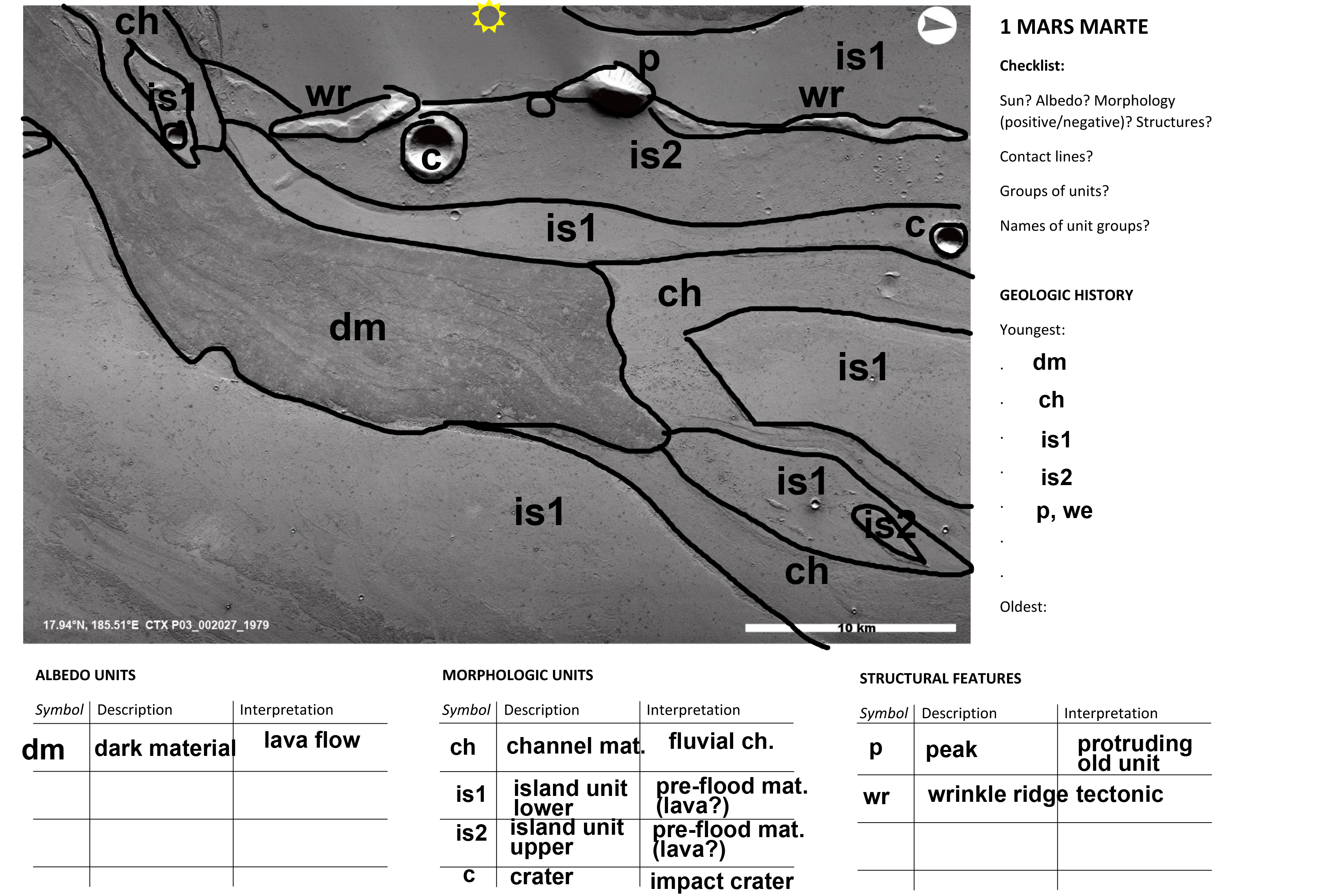
Handout_3 – No1. Marte Valles, Mars:
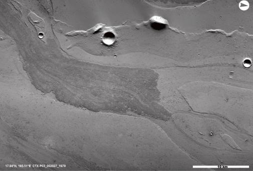
Lava flows into outflow channel with streamlined forms. Peaks and wrinkle ridges protrude
from the underlying old surface. Crater rims may be also inundated by younger lavas that mask smaller craters. In general, the units are young as shown by the lack of craters. is2 is
the most densely cratered and therfore the oldest unit. It was partially flooded by is1 lavas
into which am outflow channel was carved, leaving some islands (of is1 lavas) dry. The
latest event was when dark flood lavas flowed into the channels.
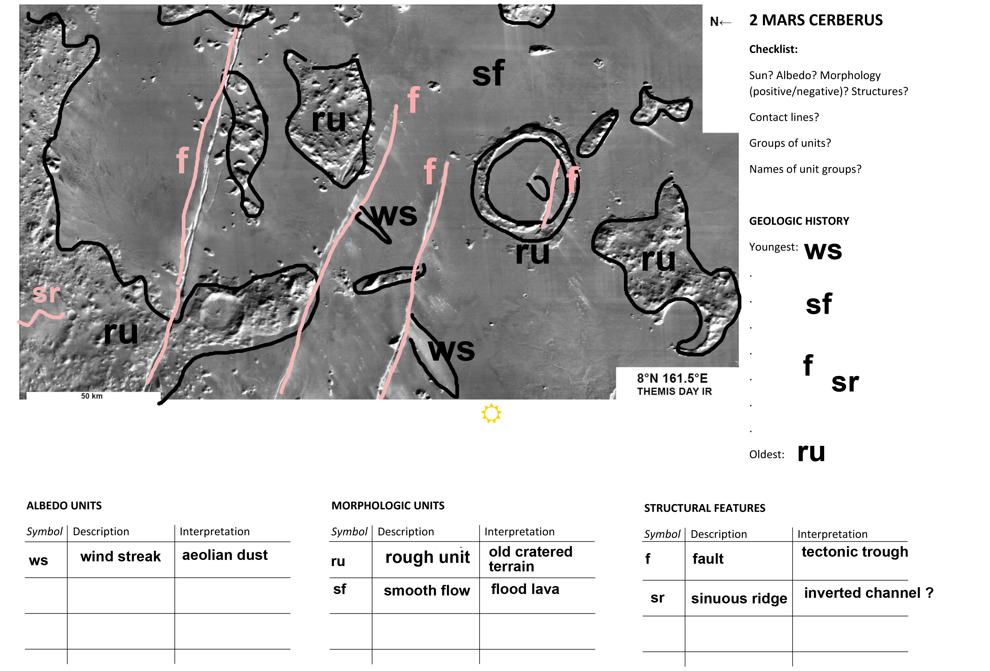
Handout_4 – No 2. Cerberus Fossae, Mars:
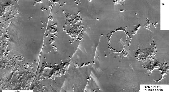
Tectonic faults, volcanic lava fields, remnant old terrain flooded by lava and aeolian wind
streaks near faults (THEMIS infrared image). Old, cratered, megbreccia highland terrain
was inundated by fresh flood lavas from originating the faults. Finally, winds blew out trapped sand from the trough, producing wind streaks. In this infrared image dark sand
appears bright because they are warmer than their surroundings.
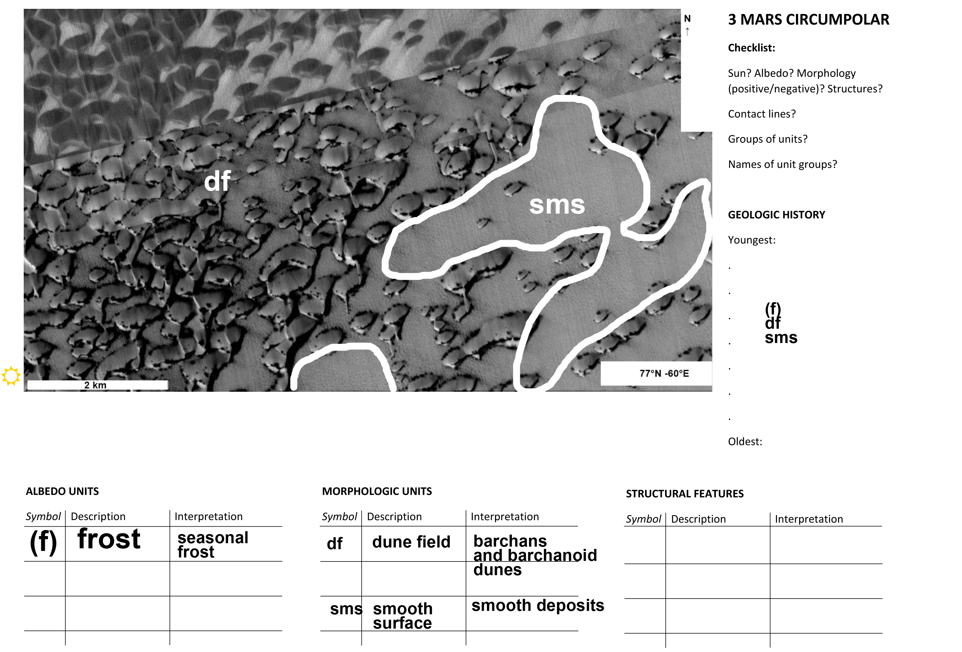
Handout_5 – No 3. Circumpolar dune fields, Mars:
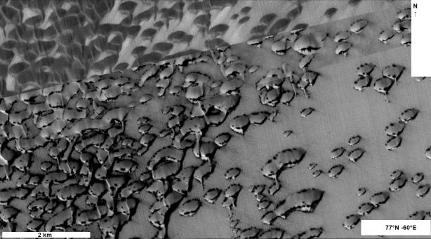
frost covered dark basaltic barchans with defrosted dark dune features, the upper part of the
picture was taken after complete defrosting. (optical image)
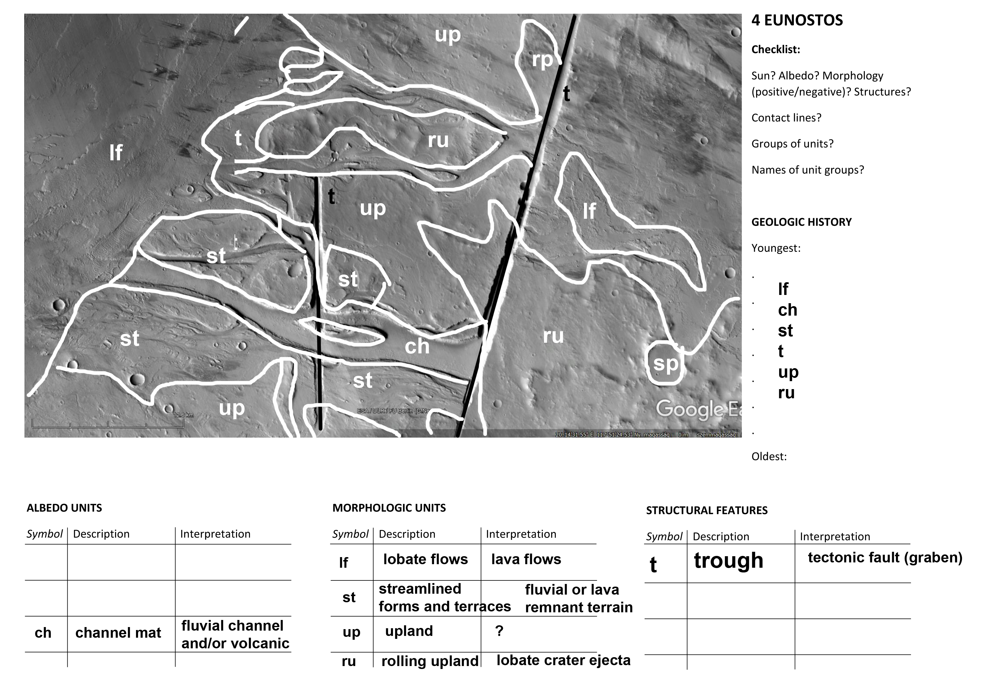
Handout_6 – No 4. Olympica, Mars:
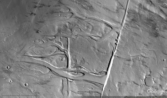
tectonic fault in volcanic terrain. The fault is the source of liquid outflows of water and lava.
Lava flows with lobate margin at the left portion. The lowermost channel floors have no
craters, they are the youngest surfaces. Dark wind streaks.
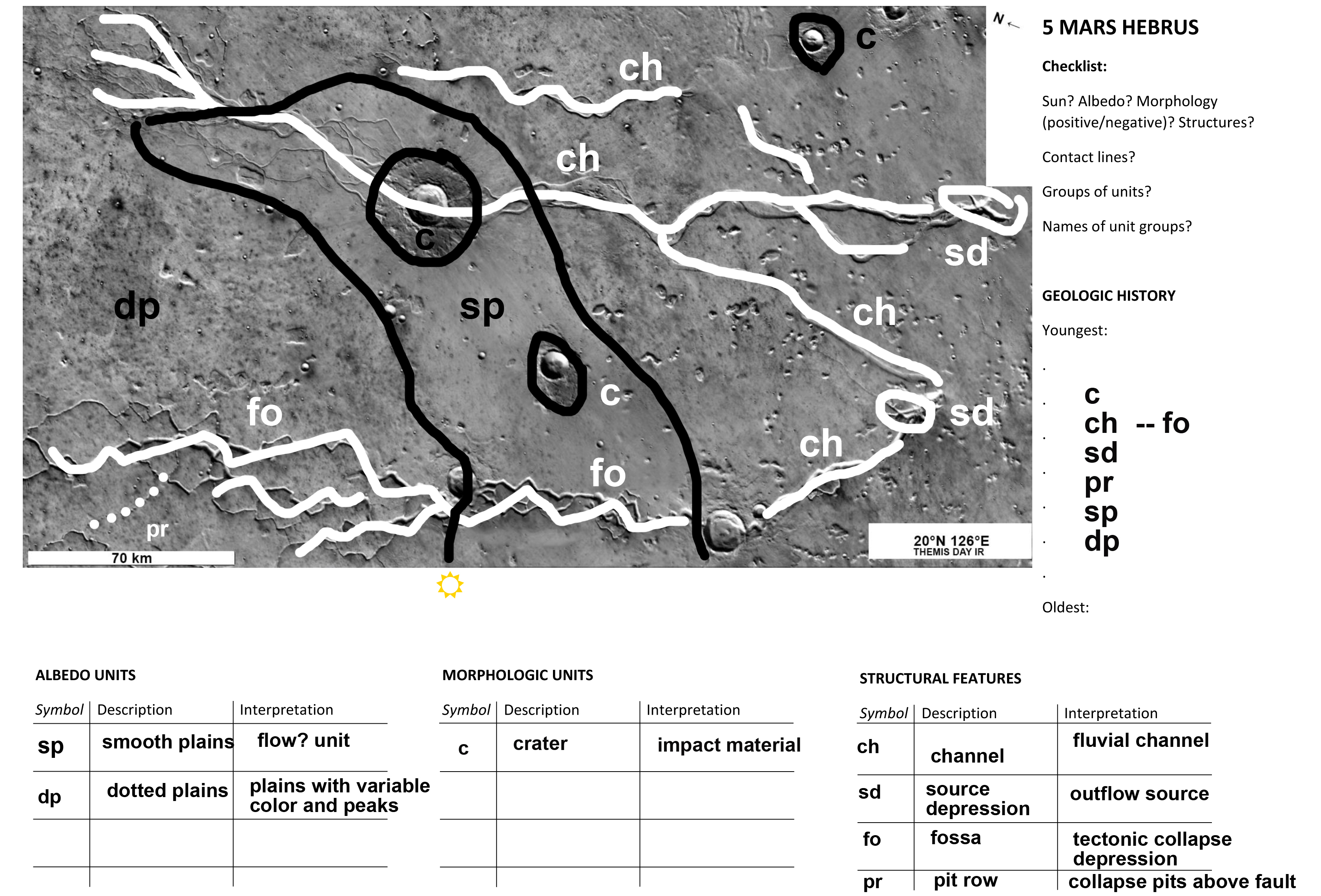
Handout_7 – No 5. Hebrus Valles/Hephaestus Fossae, Mars:
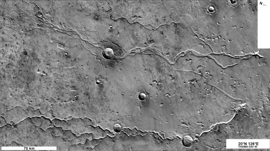
two types of channels near Elysium volcano: Hebrus is a sinuous fluvial feature, Hephaestus is a zigzag shaped tectonic feature formed by collapse and fluvial action. Some pit rows also visible. Both channels have similar sources at their right termini. Lobate ejecta craters overly
channels, covering them with a thin veneer of ejecta.
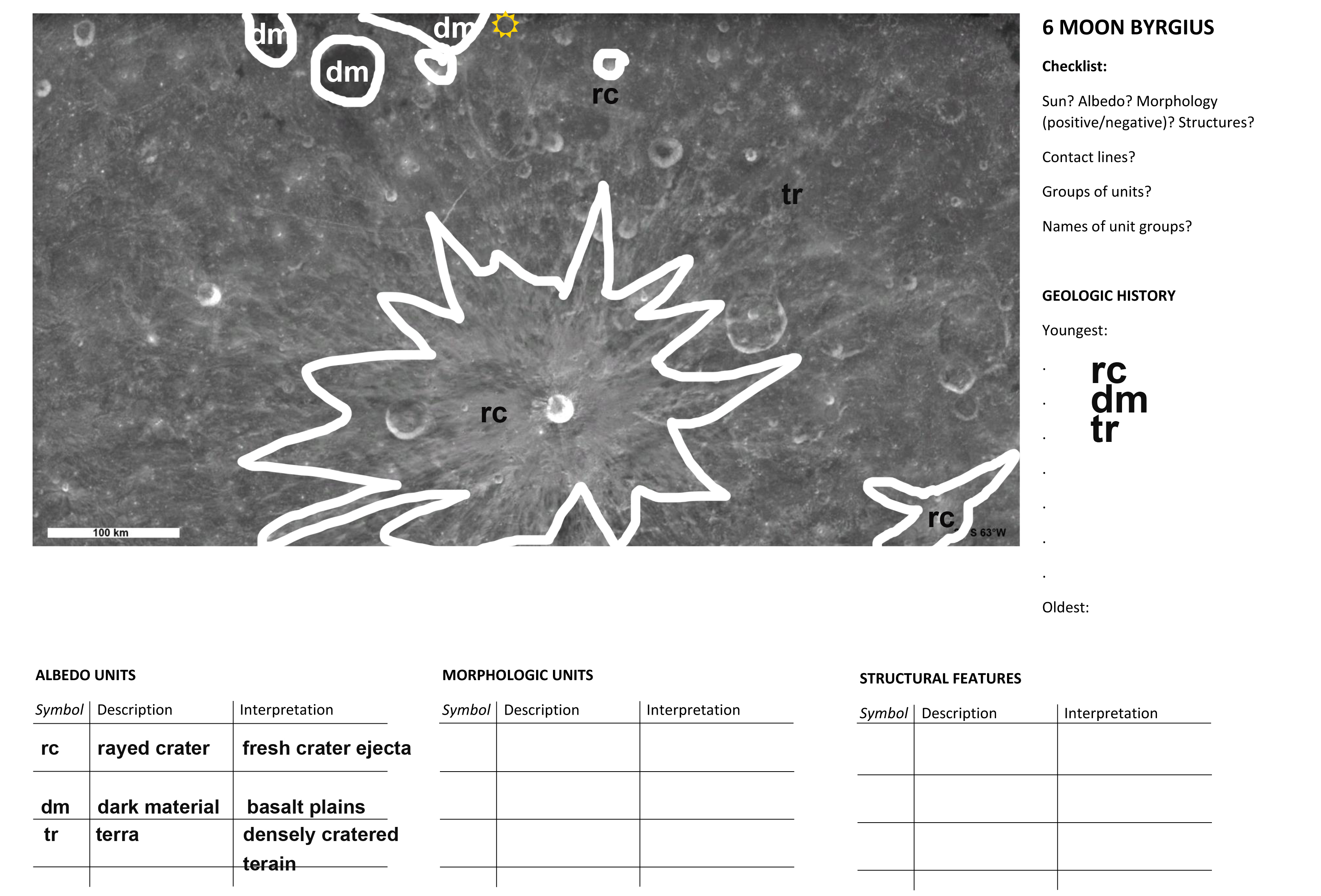
Handout_8 – No 6. Byrgius crater, Moon:
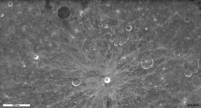
High-sun (noon) image of a cratered lunar terra (highland). The prominent crater with rays is a young crater adjacent to a hardly visible very old, degraded crater. Circular dark feature
is a crater filled with lava.
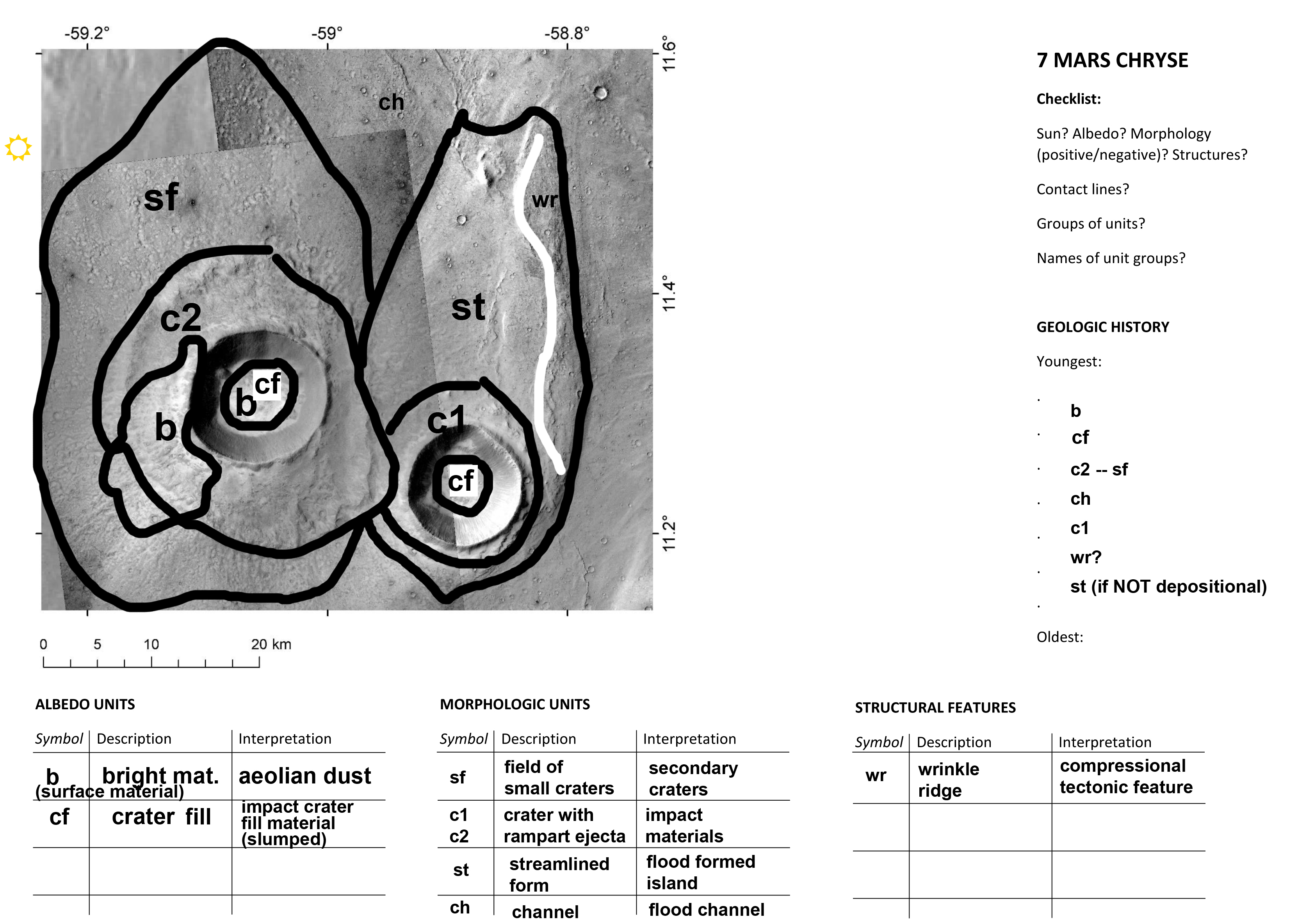
Handout_9 – No 7. Chryse Planitia, Mars:
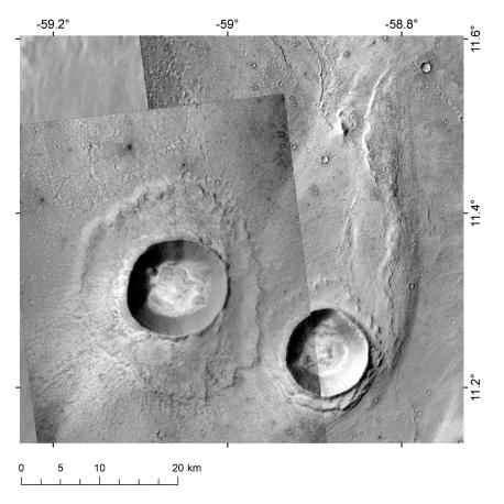
two craters of different ages. The crater on the right is older, shaped by a channel that flowed to the north, creating a streamlined feature. The left hand crater is younger, formed after the floods, and produced a dense secondary crater field. Bright dust is trapped inside the craters and is blown outside of the left hand crater (at 7–11hours), showing the dominant
wind direction.
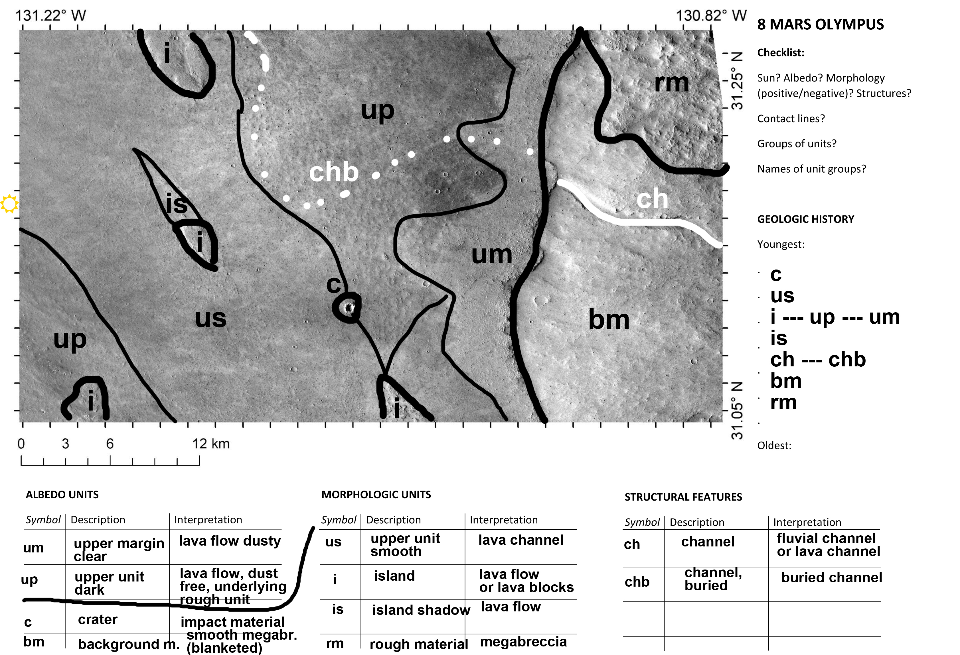
Handout_10 – No 8. Olympus Mons region, Mars:
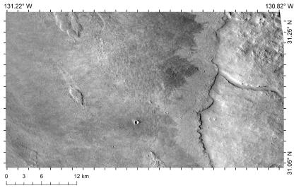
volcanic terrain with distinct lava flows. A channel is buried and streamlined features formed within younger flow whose orientation suggest a SE-NW flow direction. Dark features due to
wind.
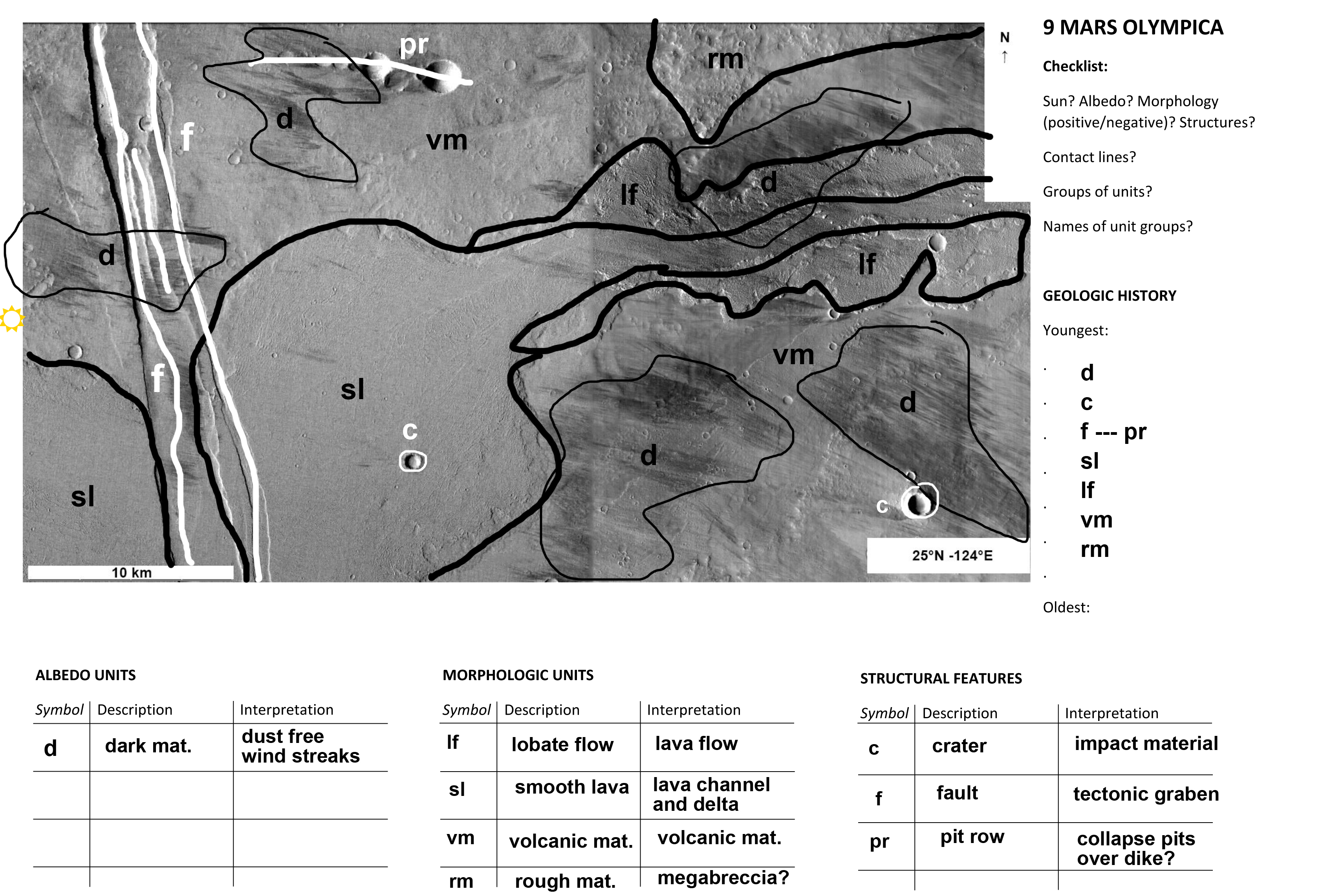
Handout_11 – No 9. Olympica Fossae region, Mars:
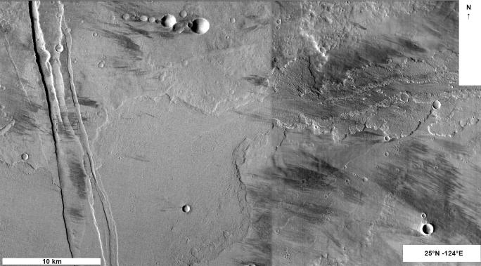
prominent lava channel from the right hand side with lobate lava flow margin, depositing lava in a lava delta that is cut by a younger tectonic graben. Flows are of different age based
on crater densities. Row of collapse pits on the upper portion of the image. Dark wind
streaks clear the surface from bright dust.
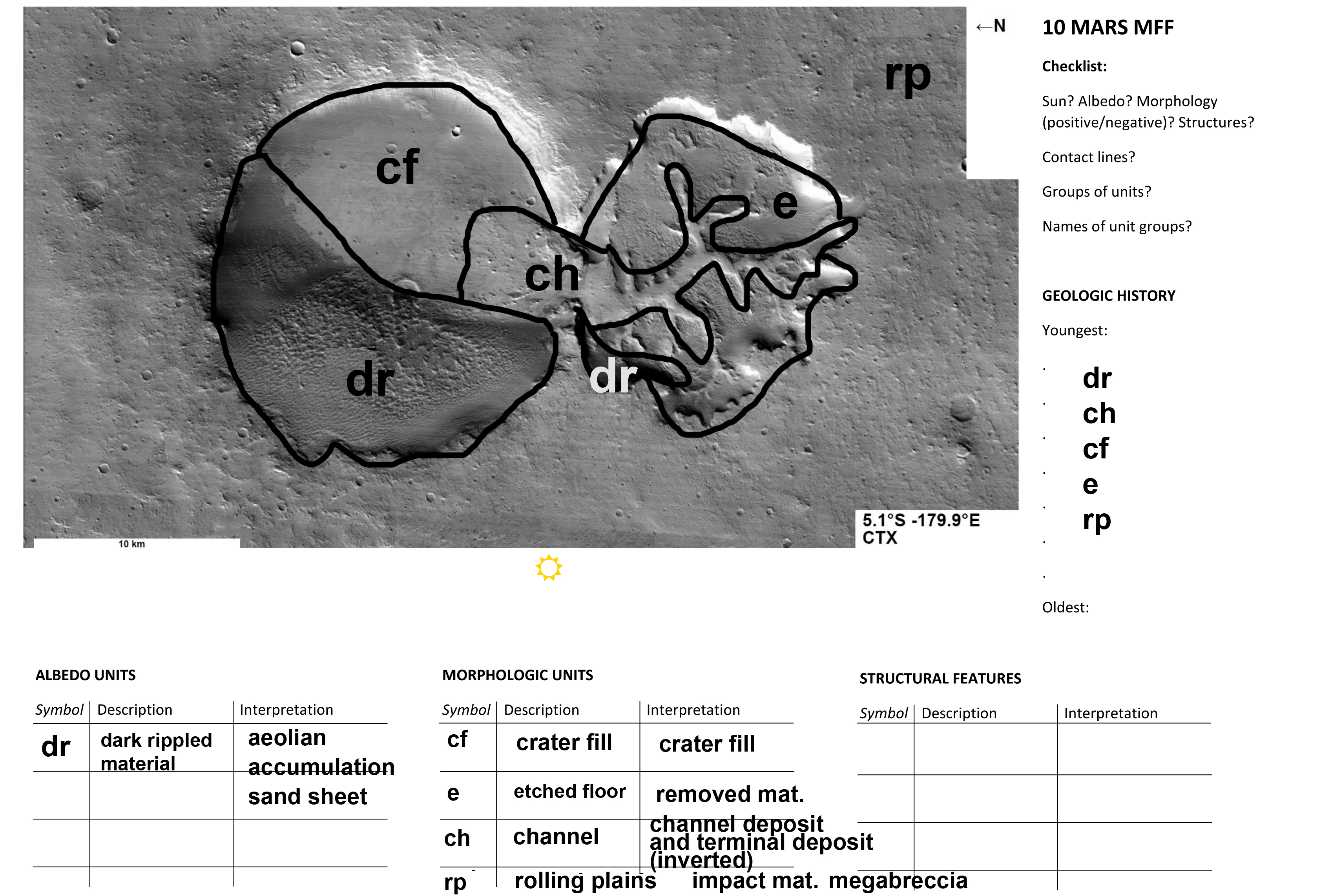
Handout_12 – No 10. Craters near Medusae Fossae Formation, Mars:
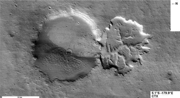
Two enigmatic depressions, near the friable Medusae Fossae Formation material sites.
Material from the right hand side crater were removed and rippled material (sand) is deposited on the lower part of the left hand crater. Material was transported from the right
hand depression to the left hand crater by channels (ridges) that are now in inverted
(positive relief) position.
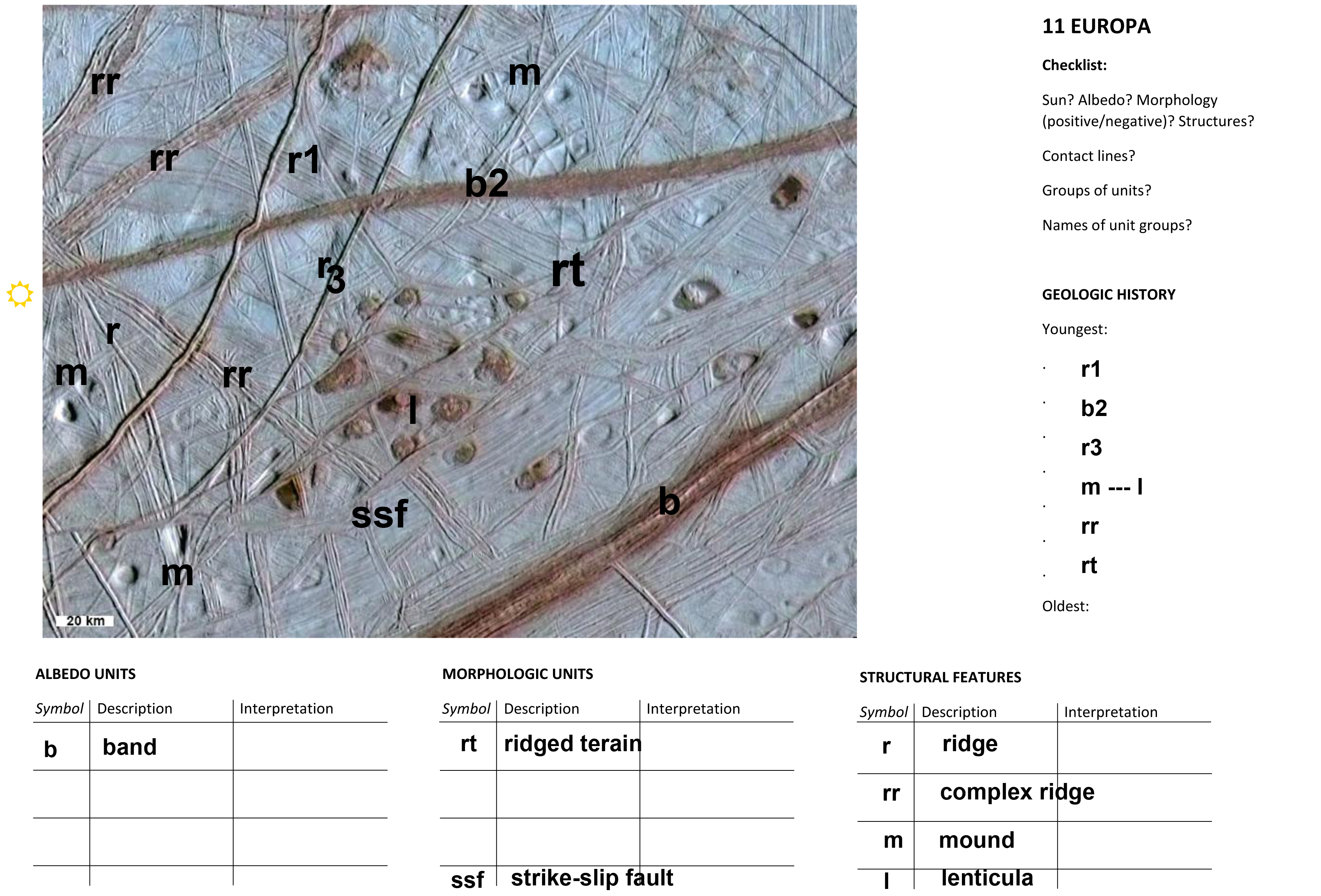
Handout_13 – No 11. Europa: Fields of lenticulae:
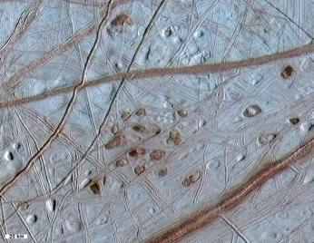
Ice crust of Europa is crisscrossed by cracks that release tectonic stresses. Lenticulae are
lens shaped features, likely where ice melted from below. Brown material likely originates
from below. The sequence of cracks can be easily reconstructed using crosscutting relationships. Several sites show strike slip faults where an older fault was displaced at
different positions along a crack.
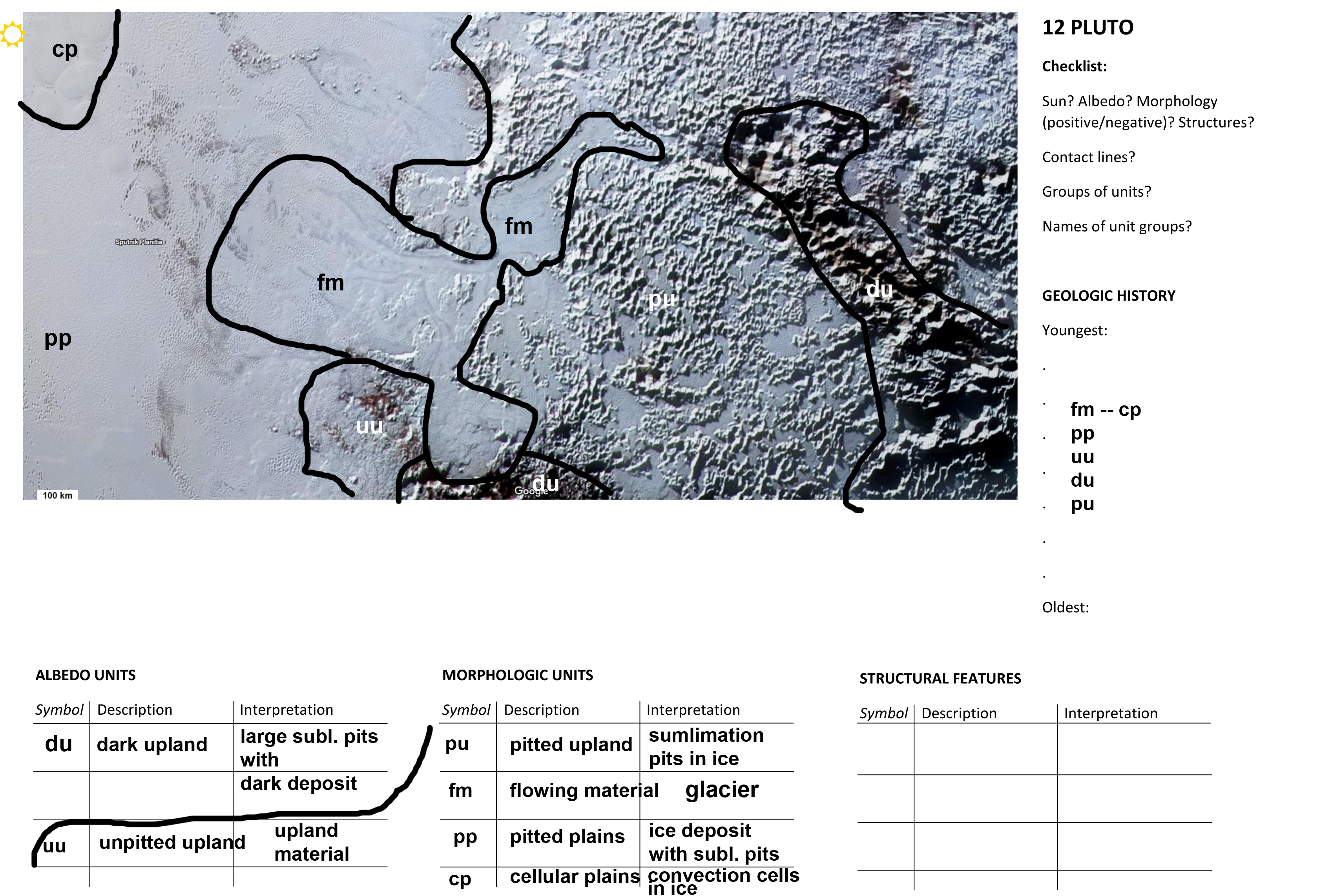
Handout_14 – No 12. Sputnik Planitia, Pluto:
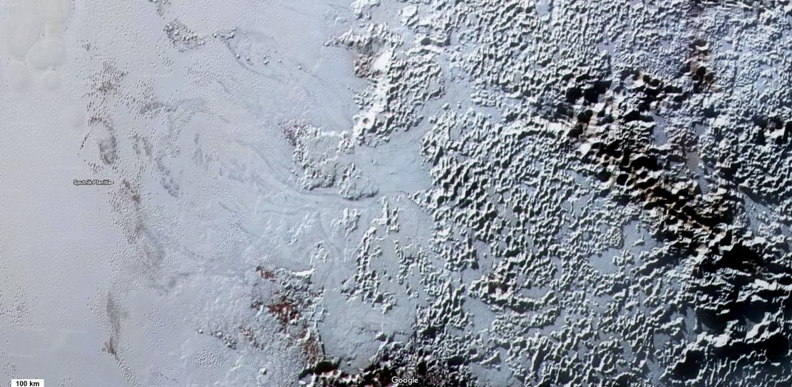
Pitted terrain likely caused by sublimation with increased sublimation creating larger pits in darker regions (darkened by a reddish blanket), likely caused by ejecta. N2 ice glaciers flow
into left hand smooth ice plains.
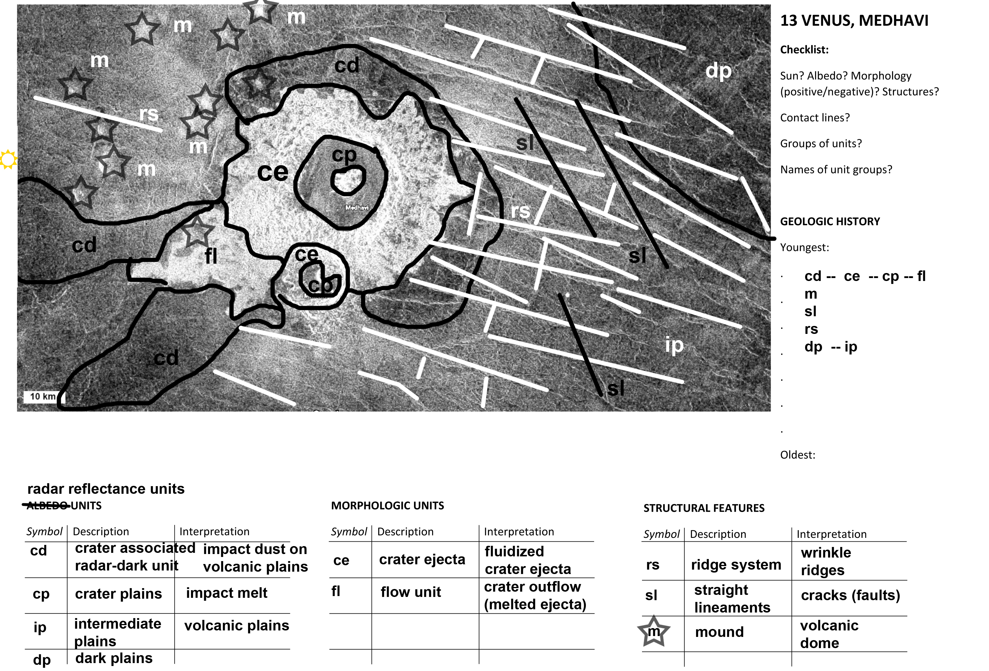
Handout_15 – No 13. Medhavi Crater, Venus:
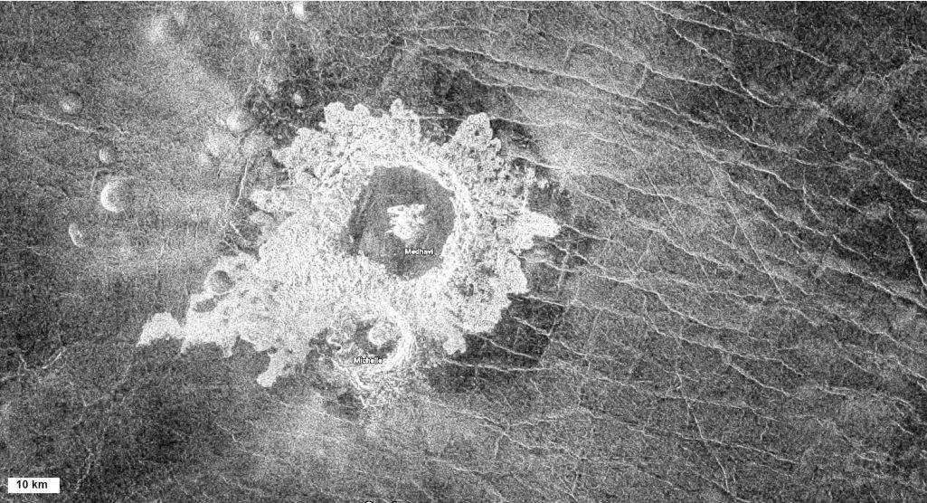
smooth lava flow terrain crisscrossed by regular network of faults. Large fluidized ejecta crater in the middle is a double crater. Melted rocky material flowed to the lower left from the
crater ejecta, while smooth impact melt filled the crater interiors. Dark markings around the
crater are caused by shock airwaves from the oblique impact. Group of mounds are probably volcanic, formed prior to impact (ejecta goes around one putative mound). (Radar
image where bright surfaces are rocky (rough) and dark surfaces are dusty (smooth). The
scene is illuminated by the spacecraft’s radar instrument, not the Sun.
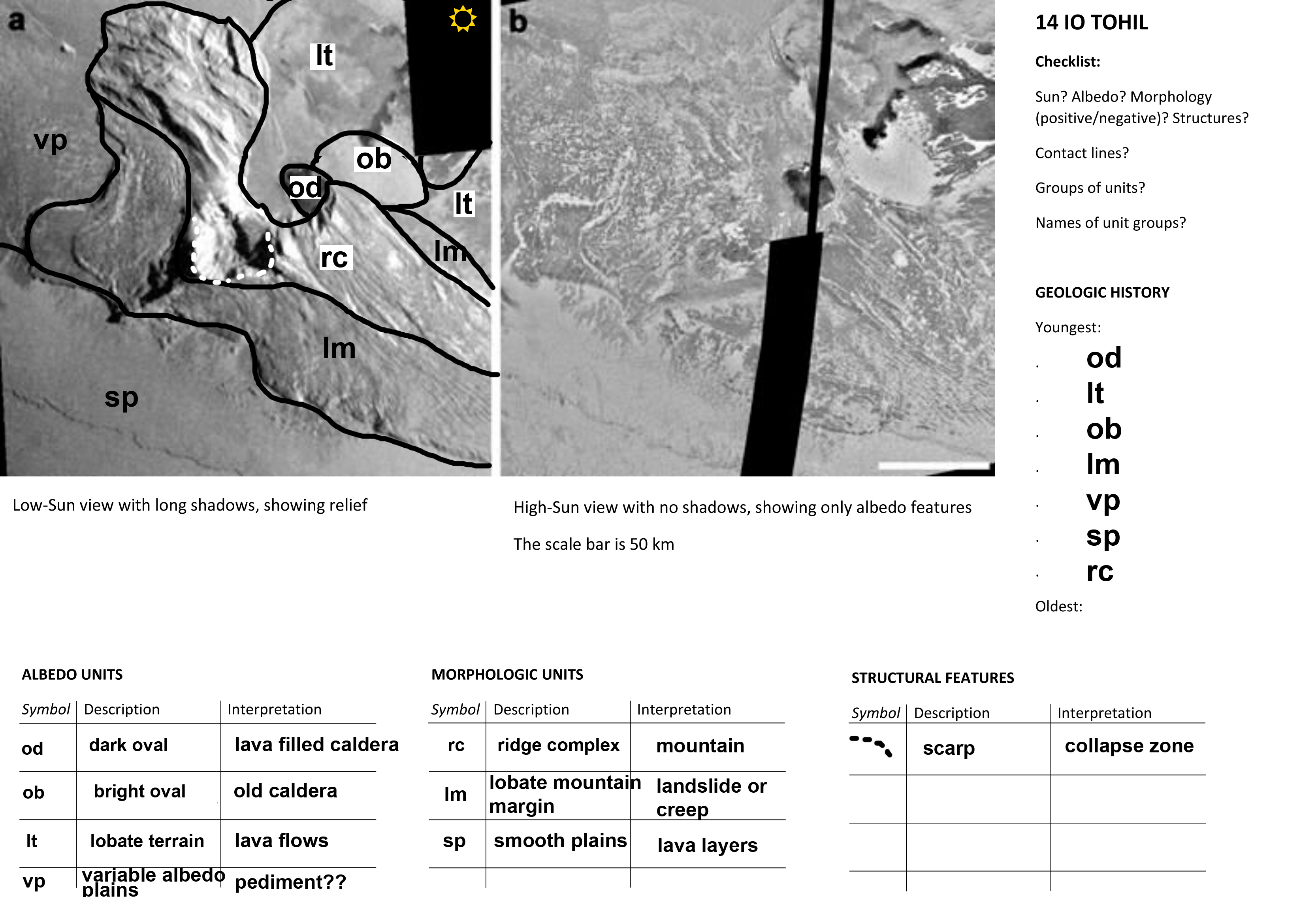
Handout_16 – No 14. Tohil Mons, Io:
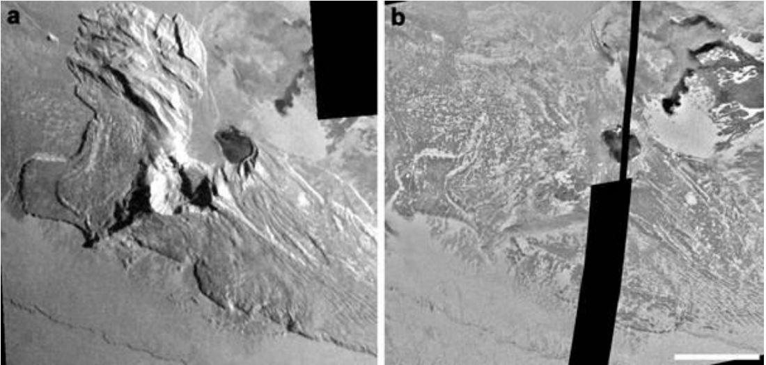
Two views show the scene under different illumination conditions: the left panel emphasizing
relief, the right panel showing only albedo differences. Dark areas have no data. A high mountain block has a deep escarpment and lobate materials, likely landslides, on its sides. The smooth plains contain calderas: a dark one may be active lava and a bright one may be
older. Overlapping lava flows arrive to the scene from NE.
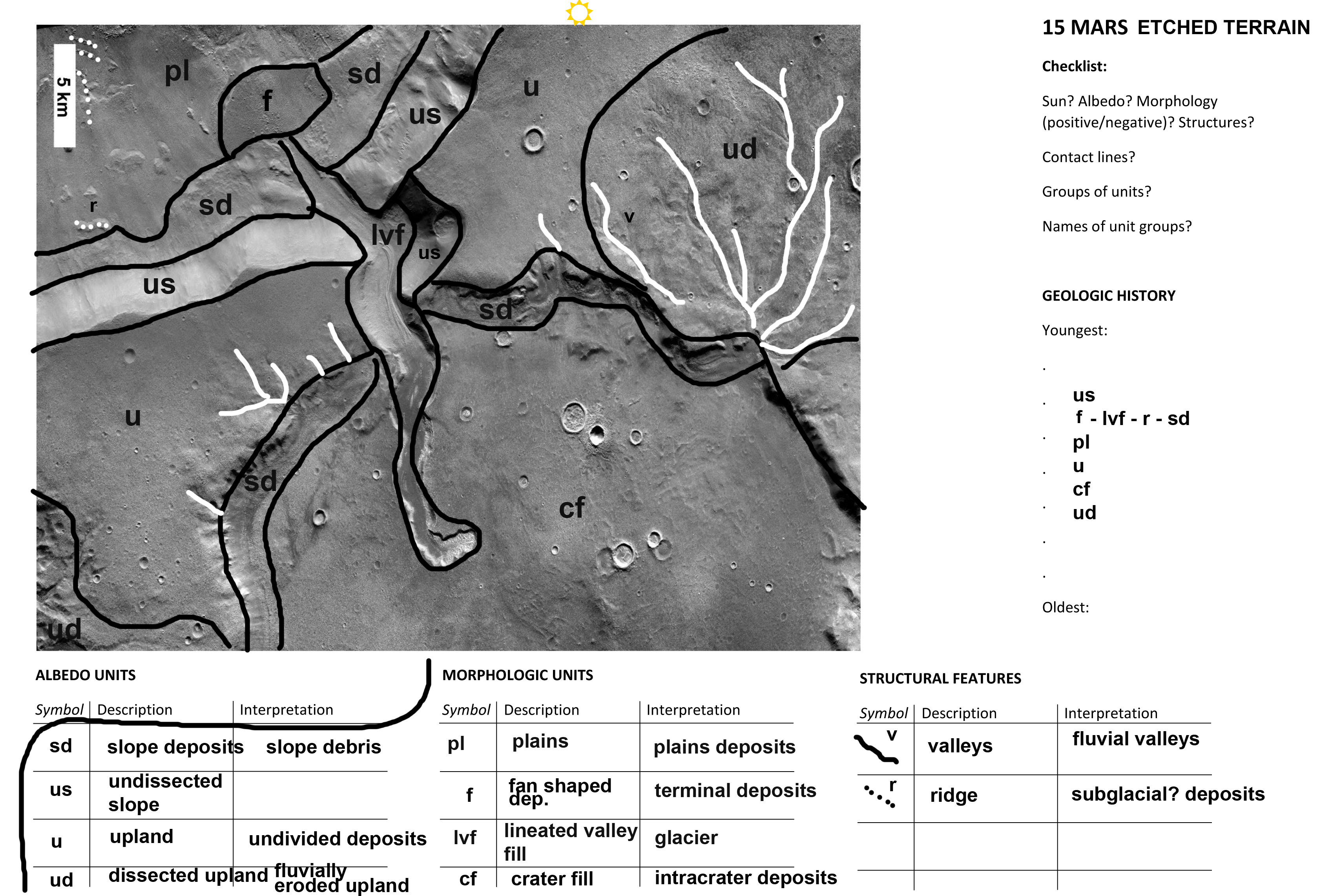
Handout_17 – No 15. Ismenius Cavus, Mars:
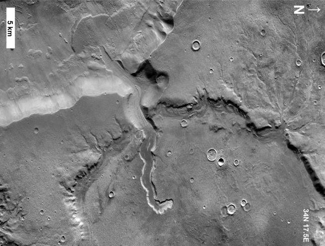
Fluvial and/or glacial features with slope deposits and lineated valley fill. Some regions are
dissected by valleys, eroding the surface to an underlying layer that reveals the oldest strata. A channel originates from inside the crater and is covered with lineated, likely glacial
material. Ridges and valleys suggest that ice formerly covered the scene.
Handouts and answer keys
After the handbook text, download the activity sheets and sample solutions here.
- Handout 1 (PDF)
 Handout 2 (PDF) · Answer key
 Handout 3 (PDF) · Answer key
 Handout 4 (PDF) · Answer key
 Handout 5 (PDF) · Answer key
 Handout 6 (PDF) · Answer key
 Handout 7 (PDF) · Answer key
 Handout 8 (PDF) · Answer key
 Handout 9 (PDF) · Answer key
 Handout 10 (PDF) · Answer key
 Handout 11 (PDF) · Answer key
 Handout 12 (PDF) · Answer key
 Handout 13 (PDF) · Answer key
 Handout 14 (PDF) · Answer key
 Handout 15 (PDF) · Answer key
 Handout 16 (PDF) · Answer key
 Handout 17 (PDF) · Answer key